USING SCIENTIFIC MOULD-MAKING TECHNIQUE TO PROVIDE YOU WELL MOULD.
The front bumper is one of the most important appearanc […]
The front bumper is one of the most important appearance parts of a car. It should not only have enough strength and rigidity, but also play a buffering role when the car collides, protect the car body, pursue harmony and unity with the car body shape, and realize its own lightweight. In order to achieve this goal, the front bumper body of the car is now made of plastic, commonly known as a plastic bumper by injection molding.
Structural analysis of plastic parts
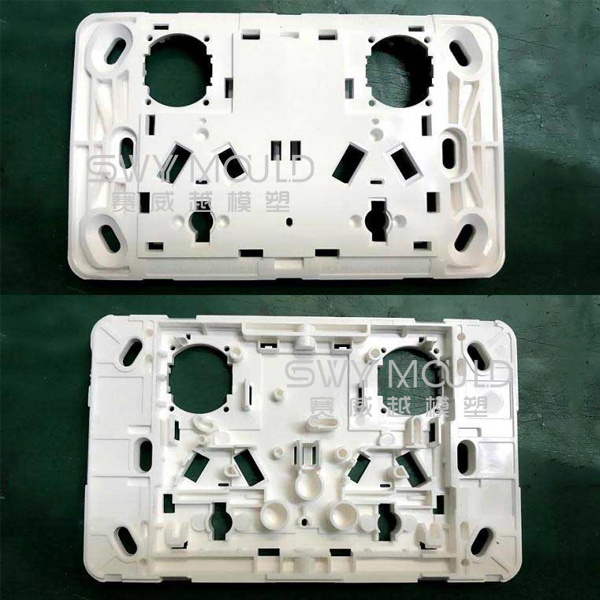
The shape of the front bumper is similar to that of the saddle. The material is PP + EPDM-T20, the shrinkage is 0.95%. PP is the main material of the bumper and EPDM can improve the elasticity of the bumper cover. T20 means adding 20% talcum powder to the material, which can improve the rigidity of the bumper cover. The features of plastic parts are:
1. The shape is complex, the size is large, and the wall thickness is relatively small, which belongs to large-scale thin-walled plastic parts.
2. The plastic parts have many bumps and penetrations, many stiffeners, and large flow resistance of injection molding melt.
3. There are three buckles on the inner side of the plastic part, and it is very difficult to pull the core laterally at each place.
Mould structure analysis
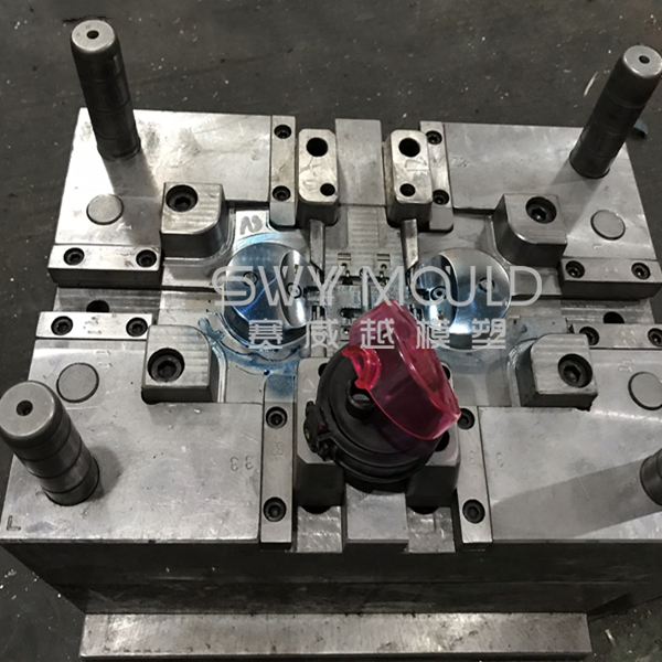
The front bumper main body injection mold adopts the inner parting surface, passes through the hot runner, and is controlled by the sequence valve. The inverted buckle on both sides adopts the structure of a large inclined roof sleeve, horizontal inclined roof, and straight roof, with the maximum dimension of 2500 × 1560 × 1790mm.
1. Design of forming part
The advanced internal parting surface technology is adopted in the mold design, The utility model has the advantages that the parting clamp line is hidden on the nonappearance surface of the bumper, which can not be seen after the assembly on the vehicle and will not affect the appearance. However, the difficulty and structure of this technology are more complex than that of the external type bumper, and the technical risk is also higher. The cost and price of the mold are also much higher than that of the external type bumper. However, due to its beautiful appearance, this technology is widely used in middle and high-grade cars.
In addition, the plastic part has a large number of through-holes, some of which are large in area. The air vent slot and void avoidance slot are designed at the place of collision, and the insertion angle is greater than 8 °, which can increase the service life of the mold, and is not easy to produce flash.
The front bumper injection mold parts and the template are made into a whole, and the template material can be pre-hardened injection mold steel P20 or 718.
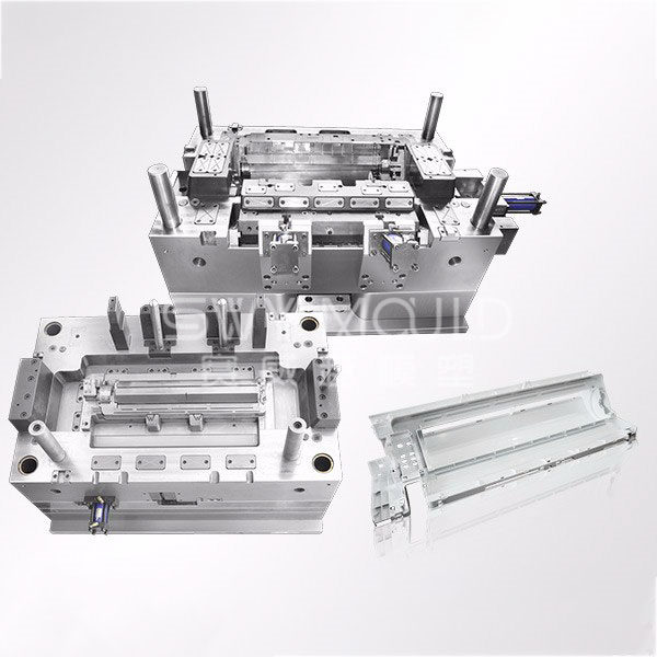
2. Design of the gating system
The whole hot runner system is adopted in the pouring system of the mould, which has the advantages of convenient assembly and disassembly, low requirements for processing accuracy, no risk of glue leakage, reliable assembly accuracy, and no need for repeated disassembly and assembly in the future, as well as low maintenance and repair costs.
The front bumper is an appearance part, and the surface is not allowed to have fusion marks. When injection molding, the fusion marks must be rushed to the nonappearance surface or eliminated, which is one of the key and difficult points in the mold design. The mold adopts the 8-point sequence valve hot runner gate control technology, namely SVG Technology, which is another advanced technology adopted by the mold. It controls the opening and closing of eight hot nozzles through the cylinder drive, so as to achieve the ideal effect of a no-weld mark on the surface of plastic parts.
SVG technology is a new hot runner forming technology developed in recent years to meet the needs of the automobile industry for large-scale flat plastic parts and the electronic industry for micro thin-walled parts. Compared with the traditional hot runner gate technology, it has the following advantages:
* The melt flow is stable, the holding pressure is more uniform, the feeding effect is significant, the shrinkage rate of plastic parts is consistent, and the dimensional accuracy is improved;
* It can eliminate the weld mark, or form the weld mark on the nonappearance surface;
* reduce the mold locking pressure and the residual stress of the plastic part;
* reduce the molding cycle and improve mould labor productivity.
The simulation data chart of the hot runner sequence valve was used in the front bumper. It can be seen from the mold flow analysis that under the normal injection pressure, mold locking force, and mold temperature, the melt flow is stable and the quality of the plastic parts is good, so the service life of the mold and the product qualification rate can be fully guaranteed.
3. Design of side core pulling mechanism
As the front bumper adopts the parting surface of internal parting, the parting line at the back buckle of the fixed mold a plate is located under the inclined top of the moving mold side. In order to avoid the risk of damage to the mold during the operation, the core pulling procedure must be strictly controlled during the opening of the mold, see the mold working process for details.
The mould adopts the complex structure of the inclined roof designed under the straight roof and the transverse inclined roof (i.e. compound inclined roof) designed inside the inclined roof. In order to pull the core smoothly, there should be enough space between the inclined roof and the straight roof, and the contact surface between the inclined roof and the straight roof should be designed with a slope of 3 ° – 5 °.
The cooling water channel shall be designed for the large inclined roof and large straight roof on both sides of the injection mold of the internal parting bumper. The side hole of the fixed mold of the internal parting bumper shall be designed with a fixed mold needle structure for core pulling.
Here we want to explain: the injection mold of the inner parting bumper and the general injection mold Different from that, the plastic part is not ejected by staying in the moving mold, but by relying on the pull hook in the process of opening. The side core pulling 43 of the fixed mold pops up during the process of opening, and the plastic part will follow the fixed mold for a certain distance.
4. Design of the temperature control system
The temperature control system design of the front bumper main injection mold has a great influence on the molding cycle and product quality. The mold temperature control system adopts the form of “straight cooling water pipe + inclined cooling water pipe + cooling water well”.
The main design points of the cooling channel of the die are as follows:
* The structure of the moving die is more complex and the heat is more concentrated, so it is necessary to focus on cooling, but the cooling channel must be kept at least 8mm away from the pushrod, straight top, and inclined top holes.
* The distance between water channels is 50-60mm, and the distance between water channels and cavity surface is 20-25mm.
* If the cooling water channel can make straight holes, do not make inclined holes. For inclined holes with a slope of fewer than 3 degrees, directly change them to square holes.
* The length of the cooling channel should not be too different to ensure that the mold temperature is roughly balanced.
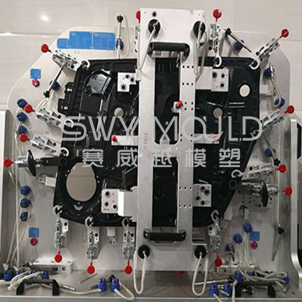
5. Design of guidance and positioning system
The mold belongs to a large thin-wall injection mold. The design of the guiding and positioning system directly affects the accuracy of the plastic parts and the life of the mold. The mould adopts square guide pillar and 1 ° precise positioning guide positioning, in which four square guide pillars 80 × 60 × 700 (mm) are used at the moving die side, and four square guide pillars 180 × 80 × 580 (mm) are used between the moving and fixed dies.
In the aspect of parting surface positioning, two cone positioning structures (also known as inner die tube position) are adopted at both ends of the die, and the inclination angle of the cone is 5 °.
6. Design of demoulding system
Plastic parts are large thin-walled parts, and the demoulding must be stable and safe. The middle position of the die adopts a straight top and ejector pin, the diameter of the ejector pin is 12mm. Because the contact area is small and difficult to return, it is easy to cause the ejector pin to collide with the cavity surface of the fixed model, so the inner parting bumper should be designed as straight as possible, and the ejector pin should be used less.
Because of the large number of push-pieces, the release force and the reset force of push-pieces are large, so the release system uses two hydraulic cylinders as the power source. See Figure 7 for the location of the cylinder. The dimension L in the figure is the distance to be delayed, which is related to the size of the fixed die reverse buckle, generally 40-70mm.
Due to the uneven surface of the moving core, all the fixed ends of the thimble and the driver cylinder are designed with a stop structure.
Taizhou Saiweiyue Mould & Plastic Co., Ltd.
Using scientific mould-making technique to provide you well moulds.

Copyright © Taizhou Saiweiyue Mould & Plastic Co., Ltd. Rights Reserved. Plastic Injection Mould Manufacturers injection molding Suppliers